The most popular advice on machining large parts is also the advice that loses shops money. Open the print, check the longest dimension against X travel, and if it fits, quote it like a bigger bracket.
That's not how a large plate, weldment, or housing behaves. Weight can defeat your crane before the spindle starts. Residual stress can bow a frame after you unclamp it. A warm part can measure in tolerance at night and fail in the morning. Add fixture design, repositioning, probing, and inspection that can't reach the far datum, and the cheap quote becomes an expensive lesson.
I'd start with a different question. Can your shop lift it, support it as stock comes off, program it without parking other work, and prove the size under the conditions the customer will use? If any answer is no, machining large parts isn't ordinary milling at a larger scale. It's a different job with different quote lines.
Table of Contents
What Your Shop Can Actually Cut
A long part isn't automatically a large-part job. The job changes when table load, crane reach, fixture mass, floor space, or inspection method changes the price. A thin panel can fit the travels and still need auxiliary supports. A compact steel block can fit and still overload the table once you add the fixture.
Baker Industries shows the far end of that scale. The Modern Machine Shop profile of Baker Industries' Emco Mecof PowerMill puts its table load capacity at 2.6 million pounds, approximately 1,179 metric tonnes, and says crews removed 1.2 million pounds of concrete and earth for the foundation pit. That facility had already operated a 32-foot horizontal five-axis machine and five-axis machines with X-axis dimensions up to 27 feet. During the reported installation, eight aluminum workpiece plates together occupied 40 feet from end to end.
You don't need equipment like that to learn the lesson. Foundations, rigging, staging, and handling are part of capacity. So is labor. A 2026 aerospace supply-chain review summarized by RapidDirect reported production targets 20% to 500% above recent levels, with 87% of programs citing supplier bottlenecks, and identified experienced five-axis programmers as especially difficult to recruit. If your one capable programmer is booked for two weeks, you don't have five-axis capacity today, whatever the machine plate says.
Capacity Gates Before You Quote
Run every oversized RFQ through these gates before you price cycle time.
Gate | Pass question | Cost if it fails |
|---|---|---|
Envelope | Does travel cover the part plus tool and probe clearance on every face? | Extra setups or a subcontract machine |
Weight and rigging | Can the crane and table carry the part plus the fixture? | Rigging time, a bigger crane, or a declined job |
Fixture and floor | Is there staging space and a support plan as stock comes off? | Fixture design hours and blocked spindle time |
Programming | Is a capable programmer free for multi-face or five-axis work? | Queue time that beats any low hourly rate |
Inspection | Will a CMM, portable arm, or laser tracker actually reach the datums? | Conditioning time and late nonconformance |
Match the machine to the geometry, not to the sales brochure. A bed mill suits long plates and open faces. A horizontal boring mill earns its keep on large bores and work on several faces. Reserve five-axis for geometry that needs tilted access or would otherwise force risky flips, and review your quoting approach for 5-axis CNC milling before you assume one setup will replace three.
Handling Is a Quote Line
Confirm the blank weight and the fixtured weight separately. They're different lifts. Walk the path from the door to the machine and check crane hook height, sling angle, lift points, forklift capacity, and turning room. A part you can lift straight up may still be impossible to rotate safely beside the machine.
Reserve staging space for raw stock, the fixture, and the finished part. If the only open floor is in front of another spindle, that blocked machine belongs in your cost thinking. The same goes for saw capacity, deburr space, and a truck or flatbed that can take the finished length.
If the part fits the travels but fails the crane, the programmer, or the inspection method, don't quote it as ordinary milling.
Partner with a shop that clears the missing gate, split the work at a clean operation boundary, or decline before the RFQ clock starts. A fast no protects your schedule. A hopeful yes can occupy your largest machine, your best programmer, and your inspection bottleneck while the margin disappears.
How to Machine a Large Part in Stages
Separate geometry creation from final accuracy. Roughing changes stress, stiffness, and temperature, so asking the same setup to create the shape and certify final size invites trouble. Put the stages on the traveler and price them as separate operations.
The staged sequence in the MetalNPI guide to specialty machining for large components leaves approximately 1.5 to 3.0 mm of stock on critical faces during roughing, then allows stabilization before finish machining. For heat-treated alloy steel, it describes roughing within 0.100 to 0.200 in of final size and stress-relieving at approximately 1,050 to 1,150°F for about one hour per inch of thickness, then finishing after hardening.

The Traveler Sequence
Review the package. Compare the drawing, CAD model, datums, material condition, stock form, and inspection callouts. Identify the blank as billet, plate, casting, extrusion, or weldment and flag missing revision or tolerance information before programming.
Decide on stress relief. Weldments, castings, and heat-treated alloy steel need an explicit yes or no. If the stock condition is unknown, don't bury the risk in machining time.
Establish rough datums. Machine enough reference surface to locate the part repeatably, but don't finish those faces yet. Record shim locations, clamp positions, and indicator readings for the next setup.
Rough symmetrically. Alternate material removal between opposing faces and open deep pockets in stages. Keep the remaining stock balanced so one side doesn't become thin and flexible while the other side is still solid.
Inspect in the middle. Check thickness, bow, twist, pocket depth, and datum drift while correction is still possible. Probe the part in its supported condition and note which clamps were tight.
Stabilize the part. Let temperature and residual stress settle, or send it for the planned stress-relief cycle. Don't rush this step because the machine happens to be open.
Finish functional features. Machine final datums, bores, sealing surfaces, threaded features, and mounting faces after stabilization. Use lighter, consistent passes and recheck datums after every flip.
Inspect and record the condition. Use a CMM, portable arm, or laser tracker that reaches the full geometry. State whether acceptance dimensions were measured clamped, supported, or free.
Where The Sequence Fails
The common failure is finishing one side completely, flipping the part, and then discovering that the first side moved. Heavy removal from the second side releases stress that the finished face can't resist. The part bows, parallel faces stop agreeing, and your machinist starts chasing datums that no longer describe the same part.
Stock form matters here. A weldment may need stress relief before serious roughing and again after major material removal. A plate with deep pockets may only need balanced roughing and a soak. A casting can hide hard spots and uneven stock, so the first pass should prove cleanup before anyone promises the final datum scheme.
Estimator's test: If roughing, stabilization, repositioning, probing, and inspection don't appear as separate lines, the quote assumes a continuous cycle that the part probably won't allow.
Build calendar time into the promise as well. Oven queues, crane availability, a second operator for the flip, and inspection scheduling can control delivery more than spindle time. A realistic traveler tells the customer when the part will be stable and measurable, not merely when the last toolpath ends.
Workholding Tooling and Toolpaths That Hold Size
Treat the fixture as part of the machine. A large part doesn't sit in a vise and behave. It spans supports, reacts to clamp order, loses stiffness as pockets open, and grows as cutting heat enters it. Your workholding plan has to manage all four changes.
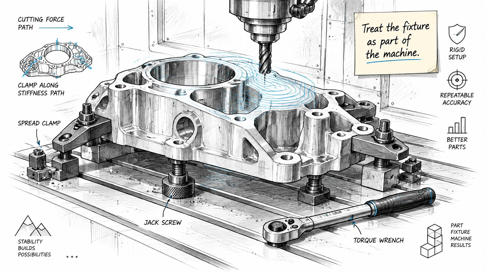
Spread clamps, toe clamps, edge supports, and jack screws along the part's stiff paths and in line with cutting forces. Tighten them in a written sequence with torque-controlled clamping where repeatability matters. One over-tightened clamp can pull a long plate into a shallow bow that disappears on release, taking your flatness result with it.
Don't box in every end. Locate the part firmly where the datum scheme requires it, then leave a controlled direction for thermal growth. Supports should prevent lift and chatter without turning the workpiece into a spring. For thin floors and long spans, bring auxiliary supports up to contact, lock them without jacking, and verify with an indicator that the surface didn't move.
Supports Must Change With The Part
The support layout that's right for a solid blank can become wrong after roughing. Removed stock changes both weight and stiffness. A jack under a newly thinned pocket floor can become a hard point, while an unsupported rib can start to sing during a finish pass.
Plan which supports move, which clamps come off for tool access, and which new supports go in before the next cut. Mark them on the setup sheet with photos. That detail sounds slow until you compare it with rebuilding a setup from memory after a weekend, a shift change, and one undocumented shim.
Tool Reach And Cutting Strategy
Use the shortest tool and holder that safely reach the feature. A short indexable face mill belongs on open faces. Save long-reach holders for walls and pockets that demand them, reduce stepdown and stepover as reach grows, and keep a fresh backup ready. A dull extended tool pushes, rubs, and deflects instead of cutting cleanly.
Tool condition deserves the same planning as tool length. Shops evaluating edge life on difficult production work may find this overview of cryogenic treatment for carbide cutting tools useful context, but no tool treatment compensates for excessive overhang, packed chips, or a holder with poor runout. Check coolant delivery at the actual tool tip, especially on long holders where through-spindle flow may not clear the cut as expected.
Program balanced roughing, then a rest pass to remove scallops and leftover corners. Finish sealing and mating faces with consistent engagement and avoid dwelling in corners. Probe or indicate datums after each flip instead of trusting the first setup. Pause to clear chips from deep pockets before finishing, because recutting packed aluminum or steel chips can damage both surface and edge.
Before cycle start, make the programmer name these items:
Clamp order and the torque or tightening method for each location
Moving supports that must be added or removed during the job
Longest tool assembly and the feature that forces that reach
Probe points after every reposition
Chip evacuation stops for deep pockets and enclosed features
If those answers aren't ready, setup hours are still a guess. I'd hold the quote until the workholding and tool list are concrete enough for another machinist to reproduce.
Sheet Metal and Finishing on Oversized Work
Large jobs often cross the aisle. A formed enclosure needs machined pads. A weldment starts as laser-cut plate and bent channels. A long panel may fit the brake but not the powder-coat oven. Quote sheet metal by alloy, temper, thickness, and grain direction, not by the generic words aluminum or steel.
The FabCon sheet-metal DFM guidelines give an inside radius of at least 1× material thickness for mild steel and 5052-H32 aluminum, 1 to 1.5× thickness for 304/316 stainless steel, and roughly 2 to 3× thickness for 6061-T6 aluminum. The same guidelines warn that using a mild-steel radius on harder 6061-T6 can cause cracking or distortion, and that bends parallel to rolling direction can require a larger radius.
Check | Rule of thumb | Example |
|---|---|---|
Mild steel or 5052-H32 radius | At least 1× thickness | Match the radius to thickness before programming the flat |
304 or 316 stainless radius | 1 to 1.5× thickness | Tighter than this marks or cracks the bend |
6061-T6 radius | About 2 to 3× thickness | A mild-steel radius is too tight |
Flange length | About 4× thickness | 2 mm sheet needs about 8 mm |
Hole to bend | 2.5× thickness plus inside radius | 3 mm sheet and 3 mm radius needs about 10.5 mm |
Slot to bend | About 4× thickness plus radius | Same 3 mm case needs about 15 mm |
Thickness window | About 0.024 to 0.250 in | Outside this, confirm the brake and laser |
Multi-bend stack-up | About 0.030 in thin, 0.040 in thick | Across three or more bends |
Flange length decides whether standard tooling can form the part. The FabCon precision sheet-metal DFM guidelines set minimum flange length at about 4× material thickness, so a 2 mm sheet generally needs approximately 8 mm to span the V-die properly. They also put bend-relief width at at least 1× thickness, with enough depth beyond the bend tangent to prevent corner bunching.
Feature placement can force a second operation. The FabCon sheet-metal bending rules use 2.5× material thickness plus the inside bend radius for hole clearance and about 4× thickness plus the bend radius for slots. On 3 mm sheet with a 3 mm radius, that's approximately 10.5 mm for a hole and 15 mm for a slot. Put a precision hole closer than that, and machining it after forming may be cheaper than scrapping distorted blanks.
Thickness also changes tolerance expectations. The Protolabs sheet-metal design guidelines publish a production range of approximately 0.024 to 0.250 inches and bend-angle capability around ±1 degree for standard work. Across three or more bends, they show representative allowances of about 0.030 inches for thinner material and 0.040 inches for thicker material. Don't let a customer carry machined-part tolerances across a four-bend enclosure without a conversation.
Finishing Can Be The Real Envelope
Ask the finisher about tank or oven size, rack capacity, lifting points, grounding, masking, and rack-mark locations before you quote. Anodize, plating, paint, and powder coat all need a way to hold the part. Cosmetic faces, sealing surfaces, threads, and close bores may need plugs or masks that take longer to install than the coating itself.
Review the full chain of outside processes and finishing while the design can still change. If the line can't take the length, price a split design, local touch-up, alternate finish, or a different vendor. A standard per-pound finishing adder won't cover custom racking, two-person handling, extra masking, or freight to a larger finisher.
Sequence matters too. Machine distortion-sensitive holes after forming when access allows it. Finish cosmetic panels after welding and grinding are complete. Protect machined datums during coating and transport. The cheapest fabrication route can become the most expensive one if finishing forces rework on features that were already accepted.
Thermal Growth, Tolerance and Quoting the Job
Say a long aluminum frame passes inspection on the machine at 6 p.m. The next morning, after it cools and comes off the clamps, the end holes no longer agree with the report. Nothing mysterious happened. The shop measured a warm, constrained part and shipped the dimensions of a cool, free one.
Start the quote from the blank, not the finished geometry. Blank size and weight determine saw capacity, crane picks, table load, fixture size, and how much material your team must turn into chips. Material lead time belongs on the schedule before programming because a late plate, forging, casting, or weldment can't be recovered with a faster feed rate.

Temperature Turns Length Into Money
The UTEC guide to thermal growth management for oversized workpieces recommends an inspection baseline near 20°C/68°F and gives this correction when stabilization is impractical. Corrected dimension = measured dimension − (CTE × nominal dimension × temperature difference).
Use that formula before you promise a number. A GLC CNC Machining guide to large CNC machines notes aluminium expands about 23 micrometres per metre per degree Celsius, so a 5°C change can shift a 1,000 mm feature by roughly 0.1 mm. That movement can consume the whole tolerance on a feature that looked comfortably inside the limit during a warm finish pass.
Large plastic parts add moisture absorption and higher thermal expansion. Cast, extruded, molded, and welded stock can distort again as machining releases residual stress. Cutting parameters alone won't solve those problems. Temperature soak, staged removal, datum strategy, controlled support, and inspection temperature become process requirements, and each one has labor or calendar cost.
Price The Span, Not Just The Feature
UTEC's practical benchmarks put typical flatness or positional capability at roughly 0.05 to 0.10 mm over 500 mm, degrading to 0.40 to 0.80 mm over 4,000 mm. Material, machine geometry, datum strategy, and inspection method can change those values substantially. They still make the central point for an estimator. A local bore diameter and a position callout across a four-metre frame aren't the same manufacturing problem.
Situation | What changes | What to quote |
|---|---|---|
Feature over about 500 mm | Flatness or position often near 0.05 to 0.10 mm | A normal tight callout may still be fair |
Feature over about 4,000 mm | Often 0.40 to 0.80 mm unless the process is controlled | Do not promise a blanket ±0.05 mm |
Shop 5°C off the baseline on aluminum | About 0.1 mm on a 1,000 mm feature | Soak time or a temperature correction |
Measured while clamped | Springback after unclamp | State clamped or free on the quote |
Cast, welded, or heat-treated stock | Bow after metal removal | Stress relief and a second setup |
Don't accept a blanket ±0.05 mm across an oversized frame because the title block says so. Ask which dimensions control assembly, sealing, bearing fit, or alignment. Keep tight tolerances on mating and functional faces, use justified GD&T elsewhere, and state whether the requirement applies clamped, on defined supports, or free. That one note can decide who pays when the part springs after unclamping.
A tolerance without a temperature and support condition is only half a requirement on a large part.
Aerospace work shows why intake detail matters. An Aerospace Manufacturing and Design article on aerospace machining techniques cited a titanium helicopter main-rotor hub measuring 66 inches in diameter and weighing more than 10,000 pounds when mounted in its fixture, produced on a system with two 1,900-millimeter tables. The same article reported that as much as 40% of jet-engine machining was outsourced. For a job shop, that opportunity only pays when the RFQ captures diameter, grade, fixture assumptions, access, required operations, and inspection before the price goes out.
Build The Estimate In Job Order
Use separate quote lines for material, saw or blank prep, fixture design and build, programming, first setup, roughing, stress relief or soak, each reposition, probing, finish machining, deburr, outside finishing, inspection, packaging, and freight. Then compare the total with a sanity check from a machining cost calculator, adjusting for the handling and stabilization steps a geometry-only estimate tends to miss.
Add the calendar constraints beside the dollars. Oven time, crane windows, programmer availability, finisher rack space, and laser-tracker scheduling can stretch lead time without adding spindle hours. I would show the customer any optional tolerance relaxation that removes a stress-relief cycle or a second finish setup, priced both ways. That gives the buyer a functional choice instead of forcing your shop to absorb an unnecessary requirement.
Finally, reconcile the quote against every customer message. Confirm alloy, temper, stock condition, revision, datums, finish, inspection report, and the clamped-or-free note. Uptool can handle RFQ intake and per-part quoting by extracting details from emails, CAD, drawings, and BOMs, taking shops from 20 minutes to 2 minutes per part for quoting while owners and estimators open, review, adjust, and send bids in minutes. In one beta test, a shop received a large quote that would have taken three days to prepare, and the prototype turned it around overnight. That speed is useful only if the estimator still spends the saved time on machine choice, setup risk, tool availability, and the conditions that make the promised tolerance real.
Stop pricing oversized work from travel dimensions and a single cycle-time guess. Uptool helps your team pull material, geometry, operations, and finishing requirements from RFQs, CAD files, drawings, and BOMs into an organized quote, so you can spend estimator time on fixturing, stress relief, inspection, and machine fit. Visit Uptool to build faster quotes that still account for what machining large parts costs.
