A repeat bracket order can look easy until the customer adds a hole pattern to one side, a pocket on the back, and a circumferential feature around the body. On a 3-axis mill, that familiar job may turn into several setups, extra soft jaws, more inspection, and more opportunities to lose the datum.
A fourth axis can simplify that workflow, but it won't automatically improve every quote. CNC milling 4 axis is a quoting and process decision, not just a machine capability. The rotary table, fixture, programming, calibration, tooling, and inspection all have to earn their place in the job.
Table of Contents
Why a Fourth Axis Changes the Whole Job
The first question isn't, “Can the shop machine this part on a 4-axis mill?” The better question is, “Will the fourth axis remove enough handling and risk to pay for itself?”
Take a repeat bracket with machined features on three sides. A 3-axis route might use a vise for the first face, a second fixture for the side features, and a third setup for the back. Each repositioning creates another chance to pick up the wrong reference, introduce fixture variation, or spend more time indicating the part than cutting it.
A rotary table changes the sequence. Once the part is located and clamped, the operator can index it to programmed angles and reach several faces without unclamping. The datum chain stays intact, and the same fixture can support multiple operations. The practical benefit is less handling, not a magical increase in spindle power.
Quoting rule: A fourth axis earns its keep when it removes expensive setups, not when it merely makes the machine look more capable.
The calculation changes with the job mix. A repeat family of hydraulic blocks, couplings, gear bodies, or multi-sided brackets may justify dedicated workholding and a proven rotary program. A one-off prototype with simple geometry may not. Programming the rotary axis, building the fixture, proving the centerline, and inspecting the first article can consume the savings from avoiding a second setup.
The broader market context supports why shops are considering this middle ground. The global CNC milling machines market was estimated at USD 84.86 billion in 2025 and is projected to reach about USD 120.82 billion by 2035, with a projected 3.60% CAGR from 2026 to 2035. The same report identifies the 4-axis segment as the fastest-growing axis configuration, placing 4-axis equipment between basic 3-axis work and more complex multi-axis machining (CNC milling machines market outlook).
That position matters for a small shop. You may need more access than a vise-mounted 3-axis process provides, but not the cost and programming burden of a full 5-axis platform. The decision should come from the prints and RFQs already arriving in your inbox.
What a 4-Axis CNC Mill Actually Does
Think of a 3-axis mill as a cutter moving around a part on a kitchen table. It travels left and right on X, front and back on Y, and up and down on Z. The part normally stays fixed while the tool creates pockets, holes, contours, and profiles from one orientation.
A 4-axis CNC mill adds a rotary axis, usually called the A-axis. In a common arrangement, A rotates around the X-axis. The rotary motion can turn the workpiece or the table, allowing the cutter to reach side features, angled holes, and geometry around a cylindrical body without manual reclamping. This basic arrangement is also described in Fictiv's overview of 4-axis CNC machining.
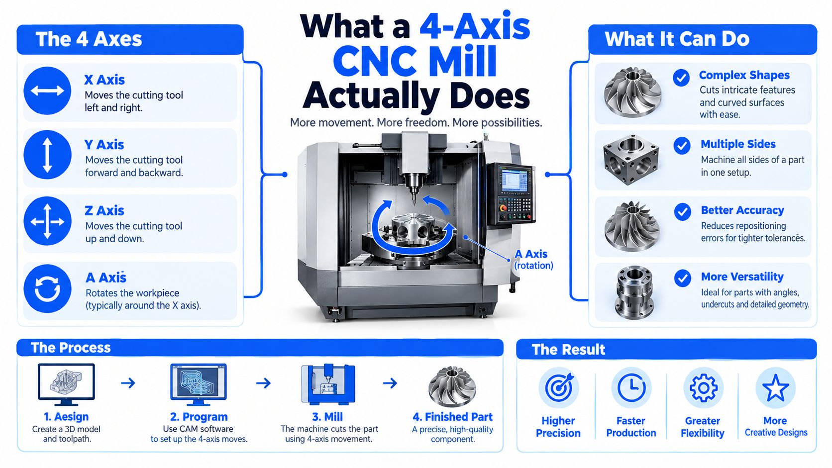
Two ways shops add the rotary motion
A trunnion-style rotary is mounted on the machine table and supports the part between rotary components. It can provide a compact, integrated arrangement, although the trunnion reduces usable work envelope and needs to be included in fixture planning.
A standalone 4th-axis unit bolts onto an existing 3-axis bed. This approach can suit a shop testing the process or moving the unit between machines, but the setup must establish the rotary centerline accurately. The chuck, tailstock, fixture plate, and part envelope all compete for space.
The controller can use the fourth axis in two distinct ways:
Indexed machining: The A-axis rotates to a fixed angle, locks, and the machine cuts with X, Y, and Z. This is often called 3+1 machining and keeps the toolpath close to familiar 3-axis programming.
Simultaneous motion: The rotary axis moves during the cut. This supports wrapped slots, spiral features, and continuous contours, but it demands more careful CAM, simulation, and machine control.
The machine still uses the three linear axes for cutting at any given point in a basic indexed process. The rotary axis changes the part's orientation or feeds the workpiece through the toolpath. That distinction matters when buying hardware because an indexer that handles four-sided drilling isn't automatically suitable for continuous contouring.
The extra axis also changes the setup datum. You need the rotary centerline, angular zero, fixture orientation, and part zero to agree with the CAM model and the machine controller. If those references don't line up, the machine can repeat the wrong position very accurately.
3-Axis vs 4-Axis and the Real Differences
A 3-axis mill remains the sensible choice for many parts. A vise, indicator, standard fixture, and straightforward CAM strategy can produce reliable work when all critical features face one direction. The process is easier to teach, easier to troubleshoot, and usually carries less fixture overhead.
A 4-axis process becomes useful when the print creates a setup problem rather than a cutting problem. If the part has features on several faces, the rotary can keep the workpiece located while the controller presents each face to the cutter. If the geometry wraps around a cylinder, continuous A-axis motion can avoid a series of short cuts and awkward reclamps.
The following comparison is a practical quoting lens:
3-Axis vs 4-Axis CNC Milling at a Glance
Factor | 3-Axis | 4-Axis |
|---|---|---|
Basic motion | X, Y, and Z linear movement | X, Y, and Z plus one rotary axis |
Workholding | Vise, fixture plate, or simple dedicated fixture | Rotary table, trunnion, chuck, soft jaws, or dedicated rotary fixture |
Face access | Usually one primary orientation per setup | Multiple indexed faces in one clamping |
Wrapped features | Limited and often requires repositioning | Suitable for indexed or continuous features around a rotary axis |
CAM workload | Generally simpler | More involved, especially for simultaneous motion |
Setup burden | Lower for simple parts, higher when many faces need machining | Higher fixture and calibration effort, potentially fewer production setups |
Best economic fit | Simple to moderate geometry and one-sided access | Repeated multi-face or cylindrical work where setup reduction matters |
A 4-axis machine isn't automatically more accurate. It adds another source of error, including rotary backlash, fixture runout, and centerline misalignment. It can improve feature-to-feature consistency when it replaces manual reorientation, but only when the rotary unit and workholding are properly calibrated.
Don't confuse 4-axis with 5-axis. A 4-axis machine has one rotary direction, so it can index around one centerline. It can't approach a part from the compound angles available on a two-rotary-axis machine. For a broader comparison of rotary-axis capability, see this 5th-axis mill guide.
The divider on a drawing is simple: does the part need access around one axis, or does it need the tool to approach from several changing angles? The first may fit 4-axis. The second may justify 5-axis or a different process.
Parts That Make Sense on a 4-Axis Mill
The strongest 4-axis candidates usually fall into one of two groups. The first group includes prismatic parts with features distributed across multiple faces. The second includes cylindrical or curved parts with details that wrap around a central axis.
A flange, hydraulic manifold, or gearbox housing may need holes, pockets, and bores on several sides. If those features share a useful datum and fit inside the rotary envelope, one fixture can replace several manual orientations. That can reduce handling and preserve positional relationships between faces.
Rotational work offers a different advantage. Couplings, sprockets, gear bodies, cam-like components, and some fan or blade forms can benefit from indexed or continuous A-axis movement. The rotary axis presents each portion of the circumference to the cutter, making slotting, drilling patterns, and wrapped machining more practical.
Typical applications span aerospace brackets and fittings, medical instrument bodies, automotive prototypes and short-run components, firearms receivers and accessories, and defense or energy valve bodies. These categories aren't automatic approvals. Material, wall thickness, tool reach, tolerances, and volume still determine whether the route makes commercial sense.
Part Geometry | Typical Industries | Motion Type | Why 4-Axis Wins |
|---|---|---|---|
Multi-face bracket or housing | Aerospace, automotive, industrial | Indexed | Reaches side faces without losing the primary fixture datum |
Cylindrical body with hole patterns | Energy, hydraulics, industrial | Indexed | Places holes around the circumference in one clamping |
Gear body, sprocket, or coupling | Automotive, machinery, defense | Indexed or simultaneous | Supports repeated angular features around a central axis |
Wrapped slot, flute, or engraving | Machinery, medical, prototype work | Simultaneous | Keeps the feature continuous around the part |
Valve body or manifold | Energy, hydraulics, industrial | Mostly indexed | Reduces reclamping across intersecting faces |
Curved or blade-like component | Aerospace, energy, specialized equipment | Simultaneous, when geometry allows | Provides controlled rotary access, though the single rotary axis can remain limiting |
A practical rule of thumb is that the rotary deserves serious consideration when four or more faces need machining with controlled datums, or when a feature wraps around a central axis. That doesn't mean every such job belongs on the machine. It means the quote should compare the rotary route against the actual cost of multiple 3-axis setups.
The gray zone is the difference between indexing and simultaneous contouring. Indexing may require only a manageable extension of a familiar 3-axis process. Simultaneous motion can change the CAM software, verification, operator skill, tooling, and inspection requirements. Price those as different processes, even when the same machine performs both.
Fixtures, Tooling, and CAM Strategies That Work
A fourth axis needs more than a rotary table. The fixture has to locate the part, clear the cutter, resist cutting forces, and leave enough access for every programmed angle.
For shaft work, a chuck and tailstock can provide support along the rotary centerline. For prismatic work, shops often choose soft jaws, a fixture plate, or dedicated nests. Soft jaws make sense for repeat work when the part profile is stable. A flexible fixture plate may be better for low-volume jobs, where a dedicated fixture would never recover its design and machining time.
A trunnion gives the setup a compact, integrated structure, but it consumes height and may restrict tool access. A standalone indexer gives more flexibility in how the shop deploys the equipment, though the operator must establish and verify the centerline each time it moves.
Build the workholding around the cutter path
Tooling choices change once the part rotates. Cutting forces act off-center, and a long tool can amplify deflection or collide with the chuck, jaws, tailstock, or rotary housing. Use the shortest practical end mill, keep the toolholder rigid, and check shank clearance at every programmed angle.
Balanced tooling becomes more important at higher spindle speeds because imbalance adds vibration to a setup that already contains rotating mass. The tool also needs enough reach to clear the fixture without resorting to an unnecessarily long stickout.
Material affects the process as much as the axis count. Aluminum, stainless steel, tool steel, titanium, and engineering plastics each respond differently to heat, chip evacuation, and edge pressure. For drilling, tapping, and milling applications, Evo Dyne Products' cutting oil guide offers a useful reference for matching cutting fluid decisions to the operation and material.
Program the rotary for the job you actually have
Start by deciding whether the fourth axis is positioning the part or moving during the cut.
Use indexed positioning for holes, pockets, flats, and features that sit on defined faces. The CAM remains close to a 3-axis workflow, and each angular position can receive its own work offset or coordinate transformation.
Use wrapped toolpaths for engraving, slot milling, and similar features that follow a cylindrical surface. Confirm how the CAM maps linear distance to rotary motion before posting the code.
Use simultaneous A-axis contouring only when the part geometry requires it. Simulate the tool, holder, fixture, and rotary envelope, not just the cutter tip.
Lead-in and lead-out choices matter on wrapped features. A poor entry angle can leave a witness mark where the cutter begins or exits. Finishing stepovers also need to reflect the material, cutter diameter, tool rigidity, and desired surface condition rather than relying on a default CAM value.
Before running unattended, prove the work zero in X, Y, and Z, then verify the rotary zero and centerline independently. A dry run at safe clearance can expose a wrong sign, wrong angular direction, or fixture collision before the first billet becomes scrap.
Tolerances, Inspection, and Where 4-Axis Falls Short
The fourth axis can improve consistency across multiple faces, but it also adds mechanical variables. Rotary backlash, chuck or fixture runout, thermal drift, and a misaligned centerline can all move a feature away from its intended location. A rotary table bolted to an existing 3-axis bed can also stack error into the process if the mounting and calibration are weak.
Published rotary-axis specifications can report resolution finer than 0.0001°, but that figure describes angular positioning capability, not guaranteed part accuracy. Actual quality depends on the table, encoder, control loop, fixture, cutter reach, table-center distance, and the effect of rotating mass on acceleration and repeatability (rotary-axis and 4-axis machining guidance).
Separate 4-axis class machine specifications report positioning accuracy around ±0.008 mm to ±0.012 mm and repeatability around ±0.005 mm to ±0.01 mm. Those figures suggest that a well-built platform can maintain tight linear performance while the rotary axis mainly adds access. They don't replace a process capability study on the actual machine and fixture (4-axis accuracy and rotary-axis considerations).
Specify the tolerance path before cutting
Don't quote a generic “tight tolerance” on a multi-face part. Identify which features share a datum, which features depend on the rotary centerline, and which surfaces need separate inspection.
A practical inspection plan may include:
Probe the rotary datum: Establish the centerline and angular zero before production.
Check a test feature: Use a known bore, pin, or test bar to verify true position through the rotary motion.
Inspect the first article: Confirm face-to-face relationships, not just individual dimensions.
Use a CMM when needed: Simultaneous 4-axis contours can require a CMM or equivalent measurement method because calipers and height gauges won't describe the full surface relationship.
The right process depends on geometry. Guidance on interpreting feature control frames, datums, and inspection requirements is available in this engineering drawing review resource.
Practical limit: A fourth axis can't solve an access problem that requires a second rotary direction.
Thin-wall parts can chatter when the rotary fixture leaves too little support. Undercuts may remain inaccessible because the A-axis only rotates around one direction. Long tools can deflect, and a simple second setup on a 3-axis machine may finish faster than a heavily fixtured rotary process.
Recent shop guidance also treats 4-axis as a middle ground that needs calibration and control discipline, rather than a universal replacement for 3-axis or 5-axis work (4-axis machining trade-offs). The same logic applies to cylindrical and multi-face work. A rotary helps with access, but complex angular geometry can still exceed what one rotary axis can reach (multi-axis CNC machining guidance).
Productivity, Cost, and Quoting a 4-Axis Job
A fourth axis belongs in the quote as a workflow change, not just a machine-rate comparison. On the 3-axis route, count each setup, fixture, indicating operation, tool change, inspection step, and likely reorientation. On the 4-axis route, include rotary fixture preparation, CAM programming, calibration, proving time, rotary cutting time, and any special inspection.
Use a simple break-even comparison:
3-axis total cost = setup labor + fixture work + programming + cutting + inspection + scrap exposure
4-axis total cost = rotary fixture work + calibration + programming + cutting + inspection + rotary maintenance or allocation
The rotary route often makes sense for repeat work because programming and fixture effort can spread across future parts. A one-off prototype carries those costs on a single part. In that case, a second 3-axis setup may cost less, even when the rotary cycle appears cleaner.
Build the estimate from the operations the part requires:
Count the faces and identify the datums.
Decide whether indexed motion is sufficient.
Estimate fixture design and build time.
Add CAM and simulation time for the rotary process.
Compare total labor and machine time with the 3-axis alternative.
Add inspection effort for rotary-dependent features.
Review material, tooling, finish, and handling requirements.
The quote should show rotary work clearly in the internal estimate. The customer can receive one combined machining line, but the estimator needs separate costs for fixture work, programming, calibration, cutting, and inspection. If the part needs a special fixture, either explain that charge or spread it across a defined repeat order. This 5-axis CNC milling quoting guide also provides a framework for separating setup, fixture, programming, and cutting costs when comparing more advanced processes.
For 4-axis parts, include deburring and edge breaking on every indexed face. Each added face brings handling and inspection time that a single-setup 3-axis part may avoid. Surface finish requirements, tool access, and part handling can also change the labor allowance, so keep them visible in the estimate.
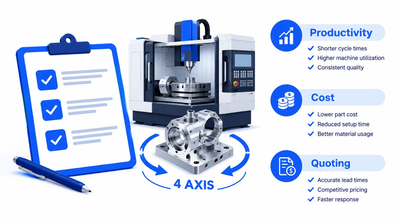
Uptool is one option for organizing this calculation inside an RFQ workflow. Its platform can parse emails, CAD models, drawings, and BOMs, then let estimators enter setup time, programming time, runtime, operations, materials, and finishing before creating a structured quote. That supports a side-by-side comparison of 3-axis and 4-axis processes while leaving the estimator in control.
The fourth axis pays for itself when it removes repeated setup work across jobs you win. Review recent RFQs, identify parts with multi-face or wrapped features, price both machining routes, and include fixture, calibration, handling, and inspection time. If the rotary option still wins after those costs are visible, it may be a sound production asset. If the simpler route costs less, quote the 3-axis process and keep the rotary off that job.
Uptool helps CNC and fabrication shops organize RFQs, extract information from drawings and CAD files, and build estimates around setup, programming, runtime, material, and finishing. Visit Uptool to see whether its quoting workflow fits the way your shop evaluates 4-axis jobs.