A customer's RFQ lands in the shared inbox with a STEP file, a drawing, a material callout, and a finishing requirement. The estimator opens the model, checks the drawing manually, searches for a similar job, asks programming for a cycle-time opinion, and waits for someone to confirm whether the right mill is available. By the time the quote is ready, a faster shop may already have won the order.
That delay usually isn't caused by a lack of machining capability. It comes from disconnected software. CNC milling software needs to do more than generate G-code. It should help move reliable information from email intake and quoting through programming, production, finishing, scheduling, and invoicing.
Table of Contents
The Hidden Bottleneck in Your Machine Shop
A capable shop can still lose profitable work before a cutter touches material. An RFQ arrives in a shared inbox, the estimator opens the 3D model and drawing, and the real work begins: checking pockets, holes, stock, tolerances, setups, material, and finishing notes.
Pricing information often sits in separate places. Material costs may be in a spreadsheet, machine rates in a personal reference file, and outside processing details in old emails. The estimator assembles those pieces into a quote, but each manual handoff adds time and creates room to miss an operation, requirement, or cost.
The inbox-to-quote gap becomes more expensive when the customer revises the job. A changed hole pattern or new coating requirement should update the assumptions behind the estimate. Without a shared part record, the estimator may price one revision while programming or production receives another.
Practical rule: A quote should preserve the same part identity, revision, material, operations, and finishing requirements that production will use later.
The useful test for CNC milling software is therefore its data flow. Can it carry an RFQ from email intake into quoting, preserve the approved information for CAD and CAM, and pass the same requirements to purchasing, inspection, scheduling, and invoicing? If staff must retype the material, revision, or finishing specification at each stage, the shop is paying for the same administrative work repeatedly.
That retyping also hides responsibility. A programmer may work from a model that no longer matches the quoted drawing. Purchasing may order material against an outdated revision. An operator may receive a program without a clear indication that it is the approved file. These are workflow failures, not toolpath problems.
The buying decision should include integration complexity, legacy systems, and interoperability, which industry coverage identifies as persistent barriers for CNC software buyers, especially smaller shops that cannot absorb long implementation cycles (industry coverage of CNC software adoption and interoperability).
A shop gains more from reliable handoffs than from another isolated feature. Faster quoting, complete cost capture, and clear revision control protect margin before production starts.
Understanding the Core CNC Software Stack
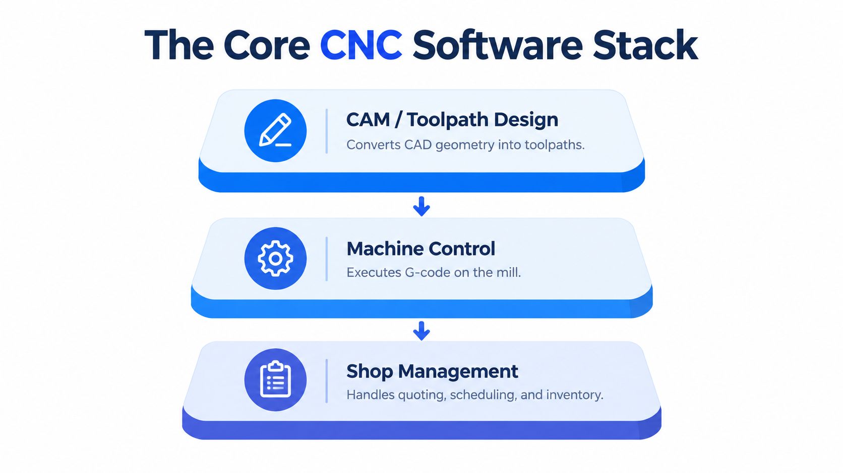
Start with a simple analogy. CAD is the blueprint, CAM is the translator, and the machine controller is the brain that executes the instructions. Shop management sits around those layers, carrying commercial and production information between them.
CAD defines the part
Computer-aided design describes the intended geometry. It may include solids, surfaces, holes, pockets, threads, bend features, dimensions, tolerances, and material notes. For an estimator, the CAD file is also a source of manufacturing clues. A deep pocket may require a long tool. A tight internal radius may limit cutter selection. Multiple orientations may indicate extra setups.
File compatibility matters because customers rarely send every job in the same format. A shop may receive native CAD files, STEP files, Parasolid files, DXF profiles, PDFs, and bills of materials. Translation can remove design intent, break references, or create uncertainty about which geometry is current.
A specialized tool can help in narrow situations. For example, a photo to DXF converter comparison is relevant when a shop needs to turn a visual outline into usable 2D geometry, but it shouldn't replace engineering review for dimensioned production work.
CAM translates intent into motion
CAM uses the CAD geometry, stock definition, tools, workholding, cutting parameters, and machining strategy to calculate toolpaths. It can generate roughing, finishing, drilling, contouring, pocketing, thread milling, and multi-axis operations.
The toolpath isn't yet the final machine language. CAM normally creates a neutral representation that needs to be processed for a particular machine and controller.
The controller executes the result
The post-processed program becomes controller-specific G-code. The control interprets that code and commands axis movement, spindle speed, feed rate, tool changes, coolant, probing, and other machine functions.
Shop management provides the missing business layer. It should connect the RFQ, quote, purchase requirements, work order, traveler, schedule, and invoice. A practical overview of this broader architecture is available in the machine shop software stack guide.
The history of this stack explains why it can feel fragmented. CAM for CNC milling emerged from numerical control research in the 1950s and 1960s, when punched cards and magnetic tape operated machine tools. During the 1970s and 1980s, microprocessors and personal computers helped turn CAM into specialized software that converted CAD models into machine instructions. By the 1990s and 2000s, mainstream industrial systems had added toolpath optimization, simulation, and multi-axis machining, as described in this history of CAM systems.
One historical benchmark is Mastercam. CNC Software was founded in 1983, and the first Mastercam version appeared in 1984. Its installed base later reached more than 280,000 seats in 2025, while another industry source reports more than 450,000 installations worldwide, a difference that likely reflects different counting methods (Mastercam history and installed-base figures).
How Toolpaths and Post-Processors Drive Profitability
A toolpath can look efficient in a CAM preview and still perform poorly on the machine. The difference often comes from engagement, retracts, direction changes, feed behavior, tool access, and the controller's response to the code.
Strategy selection is therefore a financial decision. Academic comparisons found that the best strategy differed by software environment. In one comparison, CATIA performed best with Back and Forth and Inward Helical paths, while Mastercam produced the lowest machining time with Zigzag and Spiral Constant overlap strategies. Other research using HyperMill pocketing paths showed that NC-code-based energy analysis can improve predictions of electrical energy demand and processing time (comparison of CAM toolpath strategies).
Match the strategy to the cut
Strategy Type | Best Use Case | Impact on Cycle Time |
|---|---|---|
Zigzag | Broad, accessible pockets and planar areas | Can be efficient when the tool maintains useful engagement |
Spiral constant overlap | Pockets or regions where smooth continuous motion is practical | May reduce interruptions and unnecessary repositioning |
Inward helical | Ramped entry and contained pocketing | Can support steady cutting where the geometry allows it |
Back and Forth | Open areas with suitable boundaries | Performance depends on retracts, linking, and machine behavior |
The table is a starting point, not a universal ranking. Aluminum, stainless steel, tool steel, plastics, and difficult alloys behave differently. A strategy that works well for a shallow aluminum pocket may create excess heat or tool load in stainless steel.
Energy deserves attention too. A shorter programmed path doesn't automatically mean lower total consumption if it creates aggressive acceleration, inefficient spindle loading, or additional tool changes. Compare simulated time with actual machine behavior, then record what happened to tool life, surface finish, and operator intervention.
Treat the post as production equipment
The post processor converts a neutral CAM toolpath into machine- and controller-specific G-code. It's the bridge between the programming system and the mill, and its quality affects motion accuracy, edit-free output, and manual intervention.
A post should match the exact machine build and controller dialect. Two machines with the same brand of control may differ in axis configuration, probing routines, tool-change behavior, rotary limits, coolant commands, or custom M-codes. A generic post that forces operators to edit every program isn't a usable production solution.
A post processor that requires routine edits has transferred programming work to the least protected point in the process, the machine control.
Validate the post on representative work. Check tool changes, work offsets, retract heights, rotary motion, canned cycles, probing, coolant, spindle commands, and program restart behavior. For complex work, machine-aware verification can add another control before the program reaches the spindle. The 5th-axis mill resource is useful when evaluating how multi-axis requirements affect the surrounding workflow.
Connecting Milling Software to the Quoting Workflow
A perfect toolpath won't help if the quote arrives after the customer has committed the job elsewhere. For many small shops, the biggest improvement doesn't come from another CAM feature. It comes from connecting the inbox to estimating.
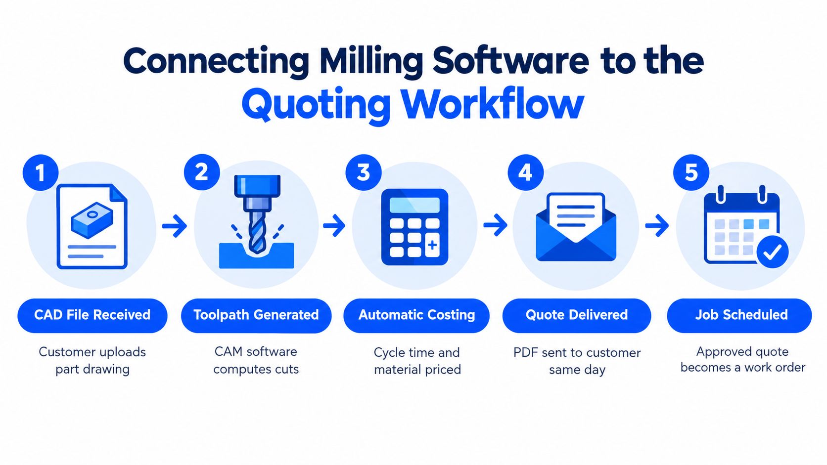
The estimator should be able to start with the RFQ, not with a blank spreadsheet. A connected workflow can identify the request, collect the CAD model, drawing, BOM, revision, material, quantity, tolerances, and finish requirements, then organize those inputs for review.
Keep automation beside human judgment
Automated geometry extraction can identify bounding dimensions, hole counts, pocket features, stock assumptions, and other inputs that influence cost. It can also route information into material and finishing databases. That reduces hand entry, but it shouldn't remove the estimator from the decision.
The best arrangement is side-by-side human and AI review. Software prepares a structured estimate. The estimator checks unusual tolerances, workholding, inspection, outside processing, and customer-specific requirements. The person remains responsible for assumptions, while the system preserves the source files and revision history.
Uptool, for example, is designed for CNC and fabrication shops to parse emails, CAD files, drawings, and BOMs into organized estimates and quotes. Its workflow includes machining inputs such as programming time, setup time, runtime, number of operations, machine selection, lead time, and final price, while also supporting finishing and downstream digital travelers. Shops evaluating that category can compare it with other CNC estimating software workflows.
The point isn't to let software invent a price. The point is to give the estimator a complete starting record.
Estimator's checkpoint: Never approve an automated quote until the material, revision, number of setups, finishing route, inspection burden, and delivery assumption have a named owner.
The quoting system should also preserve the customer conversation. If a finish clarification arrives in a reply, that message belongs with the RFQ. If the customer sends a revised drawing, the system should identify the revision rather than burying it in an email thread.
A good handoff creates a work order without retyping the quote. The approved material, operations, estimated time, outside services, and delivery promise should flow into production planning. That's how the value of CAM extends beyond toolpath creation.
The workflow below shows what that handoff should look like in practice.
Handling Sheet Metal and Finishing Specifications
Many machine shops also quote sheet metal fabrication, machined components with secondary operations, and parts that require anodizing, plating, or other finishes. CNC milling software won't calculate those requirements correctly unless the workflow captures them as structured manufacturing inputs.
Start with design rules that affect setup time. Protolabs recommends using a uniform bend radius, such as 0.030 in., across a single sheet metal part because consistency reduces machine setups and accelerates production (sheet metal bend-radius guidance).
That rule belongs in design review and estimating. If a part uses several bend radii, the estimator should account for the tooling and setup implications rather than treating the bend callout as a cosmetic detail.
Make finish requirements measurable
A quote should identify the process, standard, color or appearance requirement where applicable, masking needs, and thickness. “Anodize” isn't enough information for a reliable outside-processing estimate.
Protolabs lists specific examples that show why the details matter:
Hardcoat anodizing: MIL-A-63576, with a minimum coating thickness of 0.002 in. (0.05 mm).
Electroless nickel: ASTM-B733, with a minimum coating thickness of 0.0002 in. (0.005 mm).
Zinc plating: ASTM-B633, with a minimum coating thickness of 0.0002 in. (0.005 mm).
These specifications come from the sheet metal finishing guide. They should be stored in the quote, purchase order to the finisher, and job traveler.
Surface roughness also needs a common vocabulary. A process guide gives typical ranges of 3.2 to 12.5 µm Ra for laser cutting, 1.6 to 6.3 µm Ra for waterjet cutting, 0.8 to 6.3 µm Ra for CNC shearing, and generally below 0.8 µm Ra for anodizing or plating (surface-finish process ranges).
Build the calculator around real work
A practical estimating system should let you configure:
Material rules: grade, thickness, stock size, and supplier pricing.
Machining operations: programming, setup, runtime, tool changes, and inspection.
Sheet metal operations: cutting, bending, forming, deburring, and hardware insertion.
Finishing routes: standard, thickness, masking, vendor, transport, and expected lead time.
Revision controls: drawing revision, customer notes, and approval status.
That structure protects margin. It also gives production a clear record of what the customer bought.
Navigating Cloud Security and Compliance Risks
Cloud-connected CNC software can improve collaboration, but it isn't automatically safe. When customer geometry, drawings, quotations, toolpaths, and production records move through connected systems, the shop owner needs to know where the data lives and who can reach it.
Recent market coverage identifies cybersecurity, export-control pressure, compliance requirements, and data security as barriers to CNC software adoption. Connected manufacturing environments can expose operations, intellectual property, and product quality to unauthorized access if access controls and data handling are weak (CNC software security and compliance coverage).

Ask where the geometry goes
Before adopting a cloud-connected platform, document the full data path. A vendor should be able to explain storage location, encryption practices, employee access, subcontractor access, retention, deletion, backups, and incident response.
Export-controlled or ITAR-related work adds another layer. A shop shouldn't assume that a platform is suitable because it uses secure login or a reputable cloud host. The relevant question is whether the complete service, support process, user access model, and data residency align with the customer's contractual and regulatory requirements.
Control access by role
Not every employee needs access to every customer drawing. Estimators may need geometry and commercial information. Programmers need manufacturing data. Operators need the approved program and traveler. Accounting needs invoice and customer details, but not necessarily unrestricted CAD access.
Use practical controls:
Role-based permissions: Give each person only the access required for their work.
Revision history: Preserve who changed an estimate, drawing, toolpath, or finish requirement.
Approval gates: Require a clear release status before a program reaches production.
Vendor review: Confirm how integrations, support staff, and third-party services handle data.
Recovery planning: Make sure the shop can restore records and continue operating after an outage.
Cloud collaboration is valuable when it removes duplicate files and uncontrolled email attachments. It becomes a liability when no one can identify the approved revision or revoke access after an employee leaves.
Connected software should reduce uncertainty, not hide it behind a login screen.
Security belongs in the buying evaluation alongside post-processing, CAD compatibility, simulation, and price. A shop that protects its customers' drawings protects its contracts, reputation, and ability to keep production running.
Building a Unified System of Record
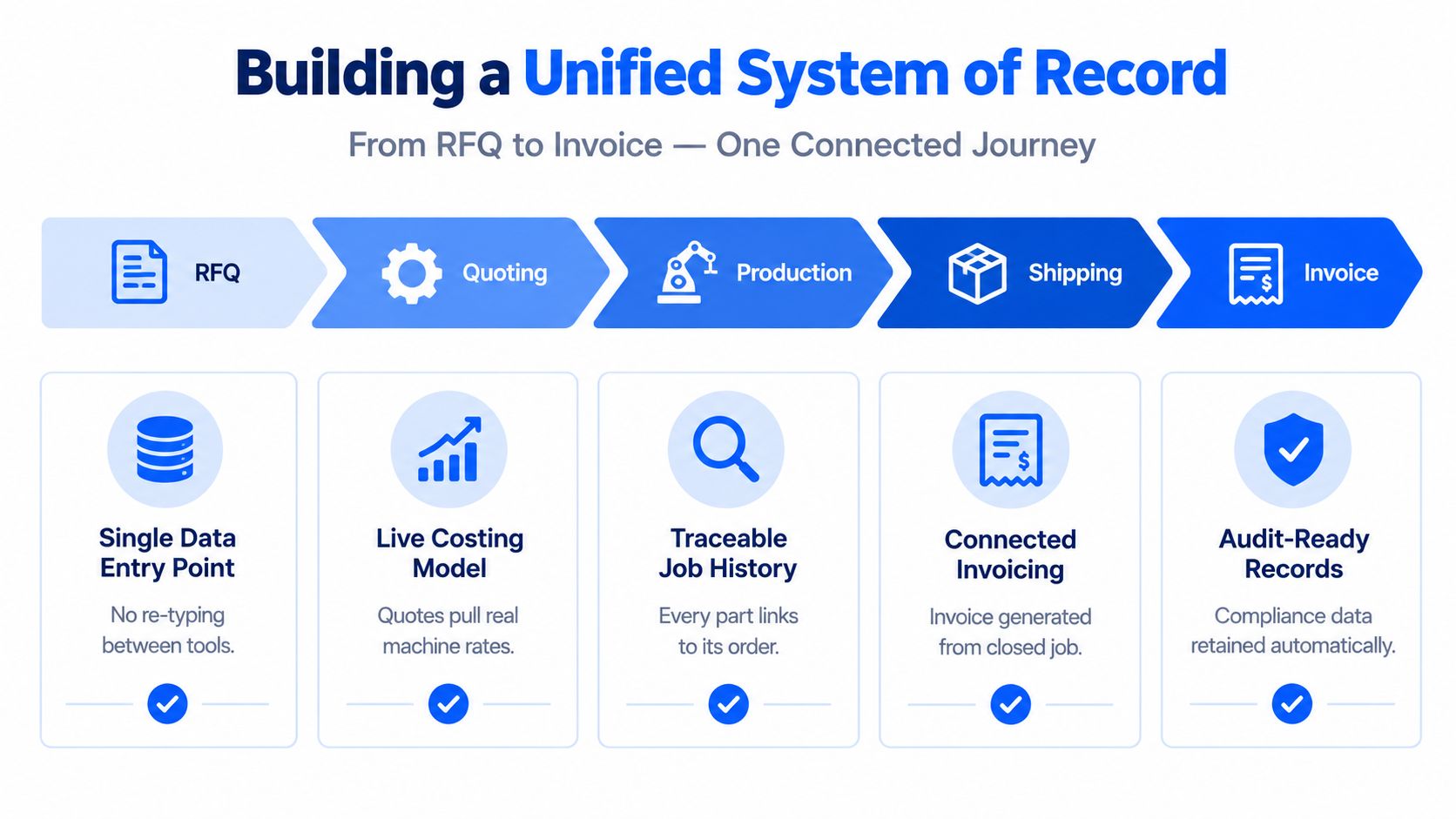
A job shop loses time when information changes hands without a reliable record. An RFQ arrives by email with a model, drawing, material, quantity, and finish. The quote becomes a work order, the work order creates a traveler, production uses the released revision, and the completed job supports invoicing. Each stage should retain the same part requirements and revision history.
A unified workflow does not require one massive application. It requires dependable handoffs between quoting, CAD, CAM, scheduling, production, finishing suppliers, and accounting. Staff should not have to retype the same information or search through email to confirm which file is approved.
Test the handoffs, not just the features
Ask each vendor to run a representative job from your shop through the complete workflow. Start with the original email and follow the information through estimating, approval, purchasing, scheduling, production, shipment, and invoicing. A polished feature list matters less than whether the system preserves the details that affect cost and delivery.
Check for:
One RFQ record: Attachments, messages, revisions, and estimating assumptions stay together.
A live costing model: Machine rates, materials, operations, outside services, and markups remain configurable.
Digital travelers: Production receives approved instructions without rebuilding the quote.
Accounting connection: Tools such as QuickBooks receive the commercial information needed for invoicing.
Traceable history: Staff can connect the completed job to its quote, drawing, program, and shipment.
CAM software can remain in service for decades, but age does not guarantee interoperability. Evaluate the fit with your existing controls, CAD tools, email habits, accounting system, and outside finishing suppliers. A platform that works in isolation may force expensive workarounds elsewhere.
The financial case is practical. Disconnected systems turn estimators, programmers, and operators into clerks. Connected records let estimators spend time on judgment, programmers review manufacturability, and operators work from released information. CAM-related end-user payments grew 6.2% to $2.9 billion in 2024 and were projected to pass $3 billion in 2025, according to CNC software market coverage. For a job shop, adoption matters only when the new system reduces re-entry and keeps work moving between departments.
Choose CNC milling software by examining what happens before and after the toolpath. If it connects quoting, CAD, CAM, machine control, finishing, scheduling, travelers, and accounting, it can improve response capacity and execution. If it only produces attractive toolpaths, the bottleneck may remain in the inbox.
Uptool connects RFQ intake, CAD and drawing analysis, machining and fabrication estimating, quote creation, revision tracking, digital travelers, and QuickBooks handoff in one workflow. Visit Uptool to review a connected quoting process that moves customer email toward production-ready information with less retyping and fewer disconnected records.